This post is follow up to my previous post about pricing changes, introduced on Microsoft Build 2024 and their cost implications for cloud storage solution.
Motivation
The Azure Cloud Adoption Framework (CAF) is Microsoft’s proven methodology for guiding organizations through their cloud adoption journey. It provides a structured approach to designing, implementing, and optimizing Azure environments based on industry best practices. CAF helps businesses align their cloud strategy with operational, security, and compliance requirements, ensuring a scalable and well-governed foundation.
Native cloud storage solutions often struggle to meet the high performance, low latency, and resilience demands of enterprise workloads. SAN solutions in the cloud address these challenges by providing highly available, scalable, and feature-rich block storage, similar to on-premises SAN architectures. SAN solutions like Pure Cloud Block Store enable seamless replication, disaster recovery, and multi-cloud mobility, making them ideal for mission-critical applications, databases, and virtualized environments that require consistent performance and data integrity.
Challenges
With adopting a SAN solution into any advanced Azure landing zone (inspired by CAF) comes few challenges that requires to be addressed.
Hidden Costs for the Data Path – Cloud networking and storage transactions can introduce unforeseen costs, especially when data is transferred across regions or via multiple peered vNETs (see more details). Understanding these costs is critical for FinOps efficiency.
No TLS Inspection or Additional Latency – Security policies enforcing TLS decryption can impact SAN replication traffic, potentially introducing performance overhead and requiring additional network configurations. Wrong design can disable to perform a TLS inspection, or in other cases bring an additional latency and lower storage performance.
Network Segregation – Proper network isolation and segmentation are crucial for security and compliance, but on the other hand a SAN solution might become a single point of failure from this perspective.
Deployment Architecture Pattern for a Shared SAN Solution
In this post, I’ll demonstrate this pattern using Pure Cloud Block Store (CBS), a SAN block storage solution designed for both Azure and AWS.
Info
Please note that the best performance and minimum costs for cloud SAN storage solutions are achieved within a single availability zone in a single virtual network deployments.
This post describes a deployments in cases where it is necessary to share a single SAN instance between multiple workloads deployed across multiple virtual networks, while adhering to CAF’s design principles and leveraging cloud benefits.
Key Features
- Optimal SAN performance: The data path is optimized, ensuring no additional latency or performance degradation is introduced
- Security isolation: Storage access is strictly limited to host VMs, preventing host VMs from communicating with each other
- Support for TLS Inspection of traffic: All standard traffic from host VMs can be a subject to TLS inspection. The only exception is the CBS data path, which is routed directly for performance optimization
- FinOps optimization: This architecture pattern is designed to minimize unnecessary vNET peering configurations, minimizing hidden costs associated with inter-vNET data transfer.
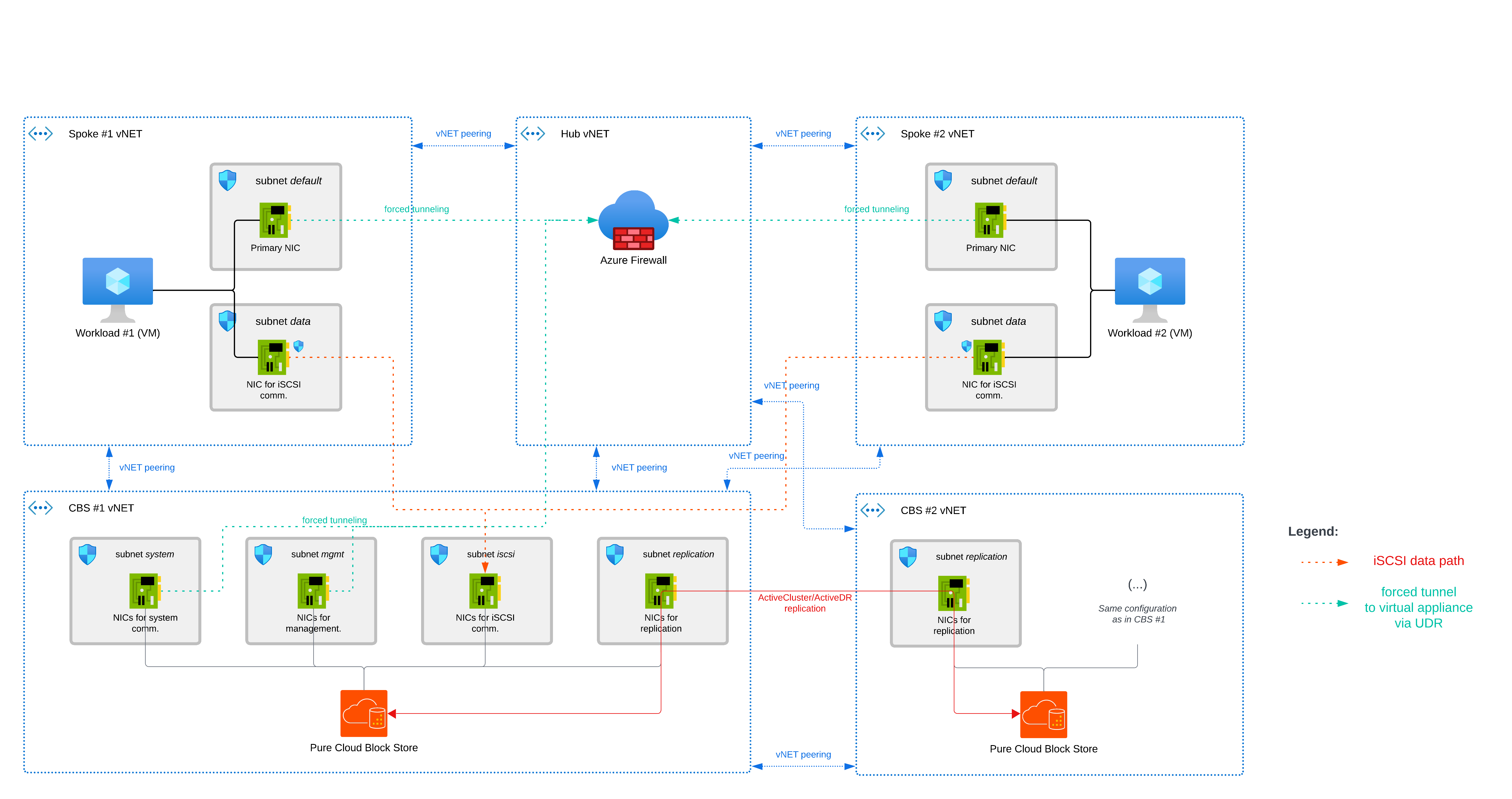
Diagram
Components
- SAN solution (Pure Cloud Block Store in our example)
- Virtual network (vNET)
- Network interface (NIC)
- Azure Firewall
- Network Security Group (NSG)
- Azure VM
Data path(s)
iSCSI Data Path
Each Host VM is in dual-NIC setup - primary and secondary NICs. A primary NIC is dedicated for standard traffic, routed to Azure Firewall and a secondary NIC is dedicated for iSCSI communication for block storage access.
Host VMs connect directly to CBS over iSCSI via a vNET Peering between host VM vNET and CBS vNET.
Replication Data Path (Between Multiple CBS Instances)
CBS supports various replication types between storage arrays, ranging from ActiveCluster (synchronous) to multiple asynchronous options such as ActiveDR and CloudSnap. These replication processes utilize dedicated network interfaces to ensure efficient data transfer.
In this setup, CBS instances replicate to each other directly via vNET Peering between the CBS #1 vNET and the CBS #2 vNET.
Details
For following examples, consider following IP ranges (IP ranges are selected to make this example easier to understand, you don’t need to follow them):
| |
NSG configurations
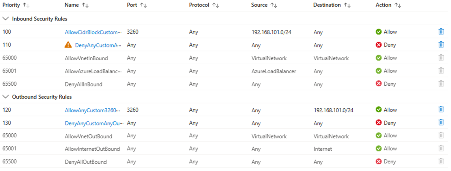
To accomplish all the needs described above, you need to configure the following Network Security Groups:
CBS #1 vNET - iSCSI subnet
Purpose: This NSG allows iSCSI traffic from NICs in the subnet only and blocks any further communication from other vNET/subnets.
| |
Example:
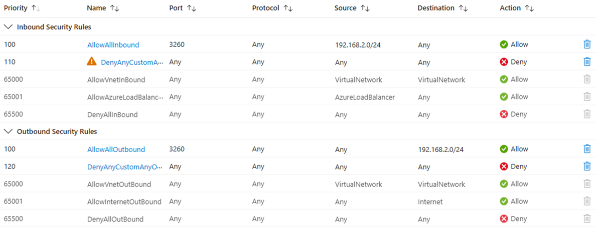
Tip
For a port configuration of inbound security rules, configure the Destination port range only and keep Source port ranges as wildcards.
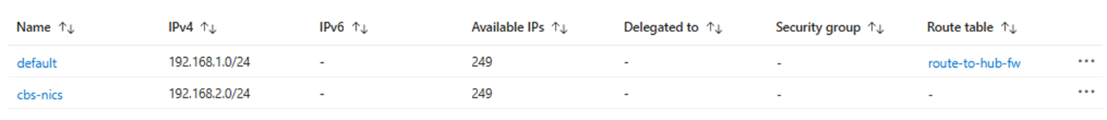
Spoke #1 vNET - NSG for VM NICs within default subnet
This NSG is for testing purposes, to make sure the iSCSI traffic to CBS will not be routed via the incorrect interface.
| |
Spoke #1 vNET - NSG for VM NICs within cbs-nics subnet
Thanks to this NSG, the iSCSI traffic can be routed via this secondary NIC and communicate with CBS, but can’t communicate with each other.
| |
Example:
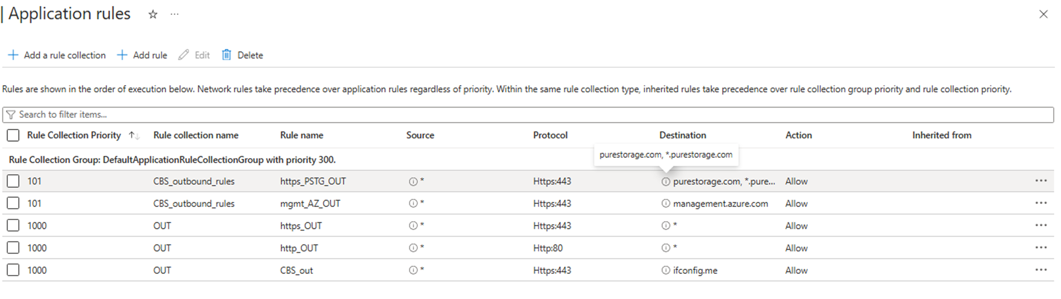
Azure Firewall configuration
All non-datapath traffic from CBS (system or management interface) can be routed through Azure Firewall or other type of virtual appliance.
Because there might be a SSL pinning in place, in the following example, we proceed with an Application rule allowing traffic to FQDN *.purestorage.com and management.azure.com without TLS inspection on Port 443 (HTTPS).
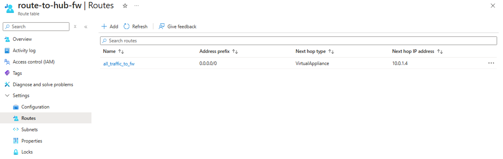
Routing configurations
Forced Tunneling
Routing to Azure Firewall is achieved via routing table, with a User-Defined Route (UDR) 0.0.0.0/0 with next hop to Azure Firewall (in our example 10.0.1.4).
CBS vNET
For achieving the forced tunneling to Azure Firewall is this routing table attached to the system and management subnets. Traffic from these CBS interfaces will be routed via Azure Firewall.
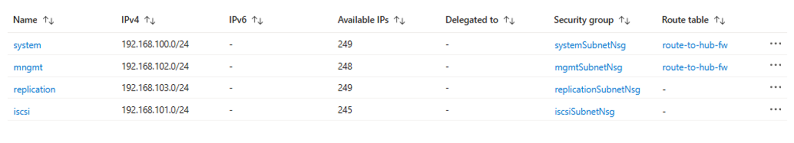
Host VM vNET
For achieving the forced tunneling to Azure Firewall is this routing table attached to the default subnet. Standard traffic from the Host VM (except for iSCSI data path) will be routed via Azure Firewall. iSCSI path will be connected directly to the CBS iSCSI subnet via vNET peering.
Host VM Routing Table
To ensure the operation system on the Host VM will know when to use secondary NIC for iSCSI traffic, you need to configure a route to CBS iSCSI interface.
Windows
Before configuring a route, we need to identify the ID of the network interface within the cbs-nics subnet.
Following commands provide information about host VMs network interfaces:
| |
To configure a persistent route, use following command:
| |
Tip
As IP address of subnet gateway use IP address: x.x.x.1
Example:
| |
Linux
Firstly, we need to identify the ID of the network interface within the cbs-nics subnet.
Following commands provide information about host VMs network interfaces:
| |
To configure a persistent route, use following command:
| |
Tip
As IP address of subnet gateway use IP address: x.x.x.1
Example:
| |
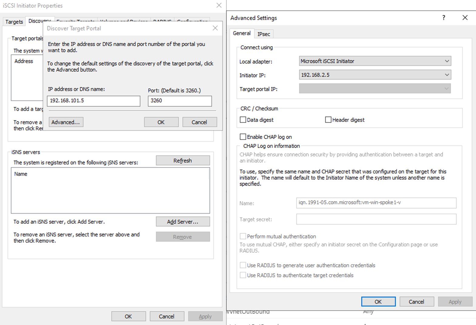
iSCSI target configuration
For connecting CBS as an iSCSI target, make sure you select the right network interface in subnet cbs-nics to be used for ISCSI initiator.
In our example it’s 192.168.2.5:
For Windows - Powershell option:
| |
Or in Windows iSCSI wizard: